Tapped Horn Experiments
There has been much talk on many of the DIY audio forums about the tapped horn. This design was recently made popular by Tom Danley at Danley Sound Labs. Tom is responsible for designing the the best performing tapped horns to date. The bandwidth he achieves in his products is as good as I have seen. It is a real juggling act between the driver and the horn to get a broad and flat response. Tom's TH115 is as good as it gets. Interestingly enough, there are many similar designs that were developed decades earlier, such as the Jensen Transflex and the JBL Air Coupler which used the 2245H driver. US Patent #5177329 shows a similar design. I would have to assume performance was poor because there are no published response plots (to the best of my knowledge) and the design quickly fell from favour. Many people are speculating and discussing the tapped horn at length, but with few exceptions in the DIY world, has anyone made some sawdust and actually built one. Through 2006 I was involved in a thesis project which attempted to accurately model the tapped horn. Many prototypes were built and many iterations of these prototypes were tried and measured. I've put together some of our findings here for discussion.
| The first tapped horn we built was this 60Hz version. This cut off was chosen for economy of timber and ease of manufacture. It was initially designed around the Eighteen Sound 10W400. This driver appeared excellent for this application, and the guess was right. Out of all the horns we built, this one had the flattest bandpass and the greatest frequency range, being essentially dead flat from 50 to 260Hz. |  |
|
Here the driver is being moved up the horn, away from the mouth and throat. |
 |
|
This plot shows the results of two different drivers being tested in this 60Hz tapped horn. |
 |
| The second tapped horn was essentially a scaled up version of the 60Hz horn. A more suitable driver was chosen for the frequency range of interest. This horn was used as a subwoofer in my main home system for a while, and now resides in my second system. The output this horn is capable of in a package one person can carry is quite astounding. |  |
|
This plot shows the results of two different drivers being tested in this 30Hz tapped horn. |
 |
|
Inside the 30Hz Tapped Horn. No bracing in this picture. |
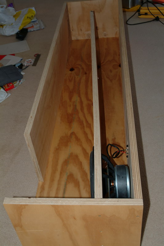 |
| Anyone who wants to make a great little tapped horn similar to this one should make a few changes. The slope of the baffle should be increased so that the throat end measurement is 48mm, giving a 150cm^2 throat. Combined with a Peerless 830564 XLS driver, I measured a flat response from 30 to 100Hz and more than 130dB output with 400W of drive, when firing from a corner. In half space the maximum output will be around 122dB at 1M and 400W. To get a feel for what this is like, it would take four 830847's in a 350 liter sealed box driven with 1200WRMS to achieve the same output as this 165 liter box with one driver at 400WRMS. The tapped horn has more output than the four driver sealed box right down to 20Hz. The Peerless 830564 is a very suitable driver in a 30Hz tapped horn, with it's 49Hz resonant frequency, good excursion and strong cone assembly. Here's a photo into the mouth of the 830564 version of the 30Hz Tapped horn. The driver will have to be mounted this way around to fit the magnet in. |  |
| Looking in the mouth of the new 30Hz Tapped Horn. | 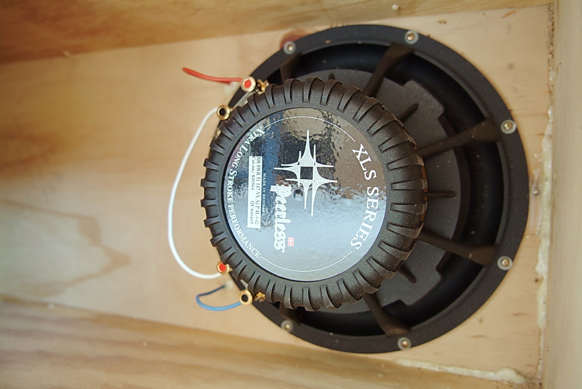 |
| The 18Hz, 30Hz and 60Hz Tapped Horns | 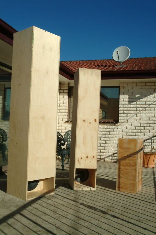 |